Mixing
Why mixing matters in bioreactors
Mixing creates a homogeneous environment in the bioreactor, needed for:
- Dispersing gases.
- Promoting heat exchange.
- Suspension of solid particles.
- Dispersing immiscible liquids.
Continuous stirred tank reactor (CSTR)
To achieve the goal of mixing, the design of a continuous stirred tank reactor (CSTR) is studied, understanding its different components.
General design ratios
| Component | Ratio | Typical range |
|---|---|---|
| Impeller diameter | – (range for good mixing) | |
| Liquid height | – | |
| Baffle width | – |
- — impeller diameter, in metres ()
- — tank diameter, in metres ()
- — height of liquid in the tank, in metres ()
- — baffle width, in metres ()
Headspace
The tank should never be filled completely with liquid, because gases are being released by microbes. Without that headspace, the gas released can cause pressure to rise and the tank to burst.
Parts of a bioreactor
Stirrer shaft
The rod on which the impeller blades are attached, and which is itself attached to a motor. The motor powers and rotates the shaft, and the shaft rotates the blades.
Baffles
Baffles are vertical metal sheets or strips attached to the inside of the tank, used to:
- Break circulatory flow of the fluid.
- Reduce gross vortex formation.
- Produce turbulence and eddies.
- Help exchange heat (coils for heat exchange are arranged around them).
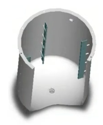
A typical reactor uses 4 baffles.
Sparger (aerator)
A sparger introduces gases into the liquid medium.
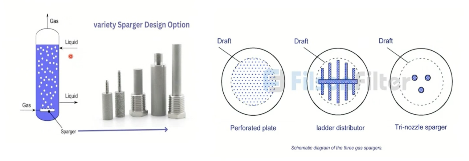
| Sparger type | Used at | Note |
|---|---|---|
| Perforated plate | Lab scale | Con: pores get blocked by fungal mycelia |
| Tri-nozzle sparger / ladder distributor (ladder sparger) | Industrial scale | Large pores — don't get blocked |
Turbulent eddies and the energy cascade
Turbulent flow in a stirred tank is not one uniform swirl — it is made up of a wide spectrum of eddy sizes, from eddies comparable to the impeller itself down to eddies just large enough for viscosity to act on them.
Energy moves through that spectrum in one direction, called the energy cascade:
- Large eddies (scale of the impeller/tank) extract kinetic energy directly from the impeller's rotation.
- Large eddies break up into progressively smaller eddies, passing kinetic energy down the size spectrum at each step.
- At the smallest scale — the Kolmogorov microscale () — eddies are small enough that viscous forces dominate over inertial forces, and kinetic energy is dissipated as heat by viscous friction. This is where essentially all the dissipation happens, not at the large scale.
Shear damage from small eddies
The Kolmogorov microscale sets the size of the smallest, most energetic eddies in the tank. When that scale approaches the size of a cell or hypha, the eddy's local velocity gradients generate high shear directly on the organism — this is why shear damage is worst in the immediate vicinity of the impeller blades, where eddies are smallest and most energetic.
- Filamentous fungi: hyphae are long and rigid, easily fragmented by small-eddy shear near the impeller.
- Animal cells: no cell wall, so they are damaged by shear levels that plant, fungal, or bacterial cells (which have a protective wall) would tolerate.
Worked example: turbulent eddies in bioreactors (GATE-style)
Question. Select the CORRECT statements regarding mixing and turbulent eddies in bioreactors:
(a) Turbulent flow is characterized by a wide spectrum of eddy sizes. (b) Large eddies extract kinetic energy directly from the impeller and transfer it down to smaller eddies. (c) Viscous dissipation of kinetic energy into heat occurs primarily at the smallest eddy scale (Kolmogorov scale). (d) High shear in the immediate vicinity of impeller blades can cause shear damage to filamentous fungi and animal cells.
Solution.
- (a) is the defining feature of turbulence used above — eddies range from impeller/tank scale down to the Kolmogorov microscale — correct.
- (b) describes the energy cascade exactly: the impeller feeds kinetic energy into the largest eddies first, and it passes down the size spectrum from there — correct.
- (c) matches step 3 of the cascade: viscous forces only dominate at the smallest (Kolmogorov) scale, which is where dissipation into heat actually happens, not at the large scale — correct.
- (d) matches the shear-damage mechanism above: small, energetic eddies near the impeller blades generate the highest local shear, damaging rigid fungal hyphae and wall-less animal cells — correct.
Answer: All four statements — (a), (b), (c), and (d) — are correct.
Power consumption
While mixing is important, bioreactors cannot be mixed at full speed. As power increases, shear stress on cells in the bulk fluid increases, and beyond a certain point the cells get lysed or damaged. This risk is highest for eukaryotes, which have no cell wall — prokaryotes and plants do have cell walls.
Units of power
One watt equals:
- (one joule per second)
- (one newton-metre per second)
- (one kilogram metre-squared per second-cubed)
Power number (Newton number, )
Power number () indicates the power required for agitating non-aerated fluids. In turbulent flow, is a constant depending on the type of impeller used; in laminar flow, is not constant.
- — power number (Newton number — dimensionless power drawn to agitate the fluid at a given speed and impeller diameter, analogous to a drag coefficient), dimensionless
- — power, in watts ()
- — density of the fluid, in kilograms per cubic metre ()
- — impeller rotational speed, in reciprocal seconds ()
- — impeller diameter, in metres ()
Before solving any problem involving , always assess whether the flow is turbulent or laminar first — is only constant in turbulent flow.
Power in laminar flow
In laminar flow, power is given by:
- — power, in watts ()
- — laminar power constant, a dimensionless constant depending on the geometry of the impeller and tank (blade pitch, blade shape, number of blades, vessel geometry)
- — dynamic viscosity of the fluid, in pascal-seconds ()
- — impeller rotational speed, in reciprocal seconds ()
- — impeller diameter, in metres ()
Impeller tip speed
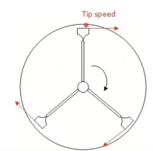
- — impeller tip speed (maximum linear velocity at the blade edge — a proxy for the shear intensity cells experience near the impeller), in metres per second ()
- — impeller rotational speed, in reciprocal seconds ()
- — impeller diameter, in metres ()
Flow number ( / )
The effectiveness of the impeller for pumping the fluid is represented by a dimensionless number, the flow number.
- — flow number (also written — dimensionless measure of pumping capacity: how much fluid volume the impeller circulates per revolution), dimensionless
- — volumetric flow rate of fluid leaving the impeller blade, in cubic metres per second ()
- — impeller rotational speed, in reciprocal seconds ()
- — impeller diameter, in metres ()
Common confusion: power number vs. flow number
Both are built from the same , , terms and are easy to swap under exam pressure — the difference is what they measure and the power on .
| Power number () | Flow number () | |
|---|---|---|
| Formula | ||
| Represents | Power drawn to agitate the fluid | Pumping capacity (volumetric throughput) |
| Power on | ||
| High value means | High shear / power draw (e.g. Rushton) | High bulk turnover (e.g. axial impellers) |
Mixing time
Mixing time should be as low as possible. If mixing time is high, when chemicals are added, the local region they are added to can shift in pH or other local conditions enough that the cells there die.
Calculating mixing time ( / )
If power is given
- — mixing time (time required for an added pulse of tracer/chemical to become homogeneously distributed through the vessel), in seconds ()
- — tank diameter, in metres ()
- — density of the fluid, in kilograms per cubic metre ()
- — volume of liquid, in cubic metres ()
- — power, in watts ()
- — impeller diameter, in metres ()
If power number is given
- — mixing time (time required for an added pulse of tracer/chemical to become homogeneously distributed through the vessel), in seconds ()
- — impeller rotational speed, in reciprocal seconds ()
- — power number (dimensionless power drawn to agitate the fluid), dimensionless
- — tank diameter, in metres ()
- — impeller diameter, in metres ()
Impeller
Axial flow vs. radial flow impellers
Axial flow impellers discharge fluid primarily parallel to the impeller drive shaft, along the vertical axis, creating top-to-bottom bulk turnover. Radial flow impellers discharge fluid perpendicular to the drive shaft, radially outward to the vessel wall, where it splits into two circulation loops — one moving upward, one moving downward.
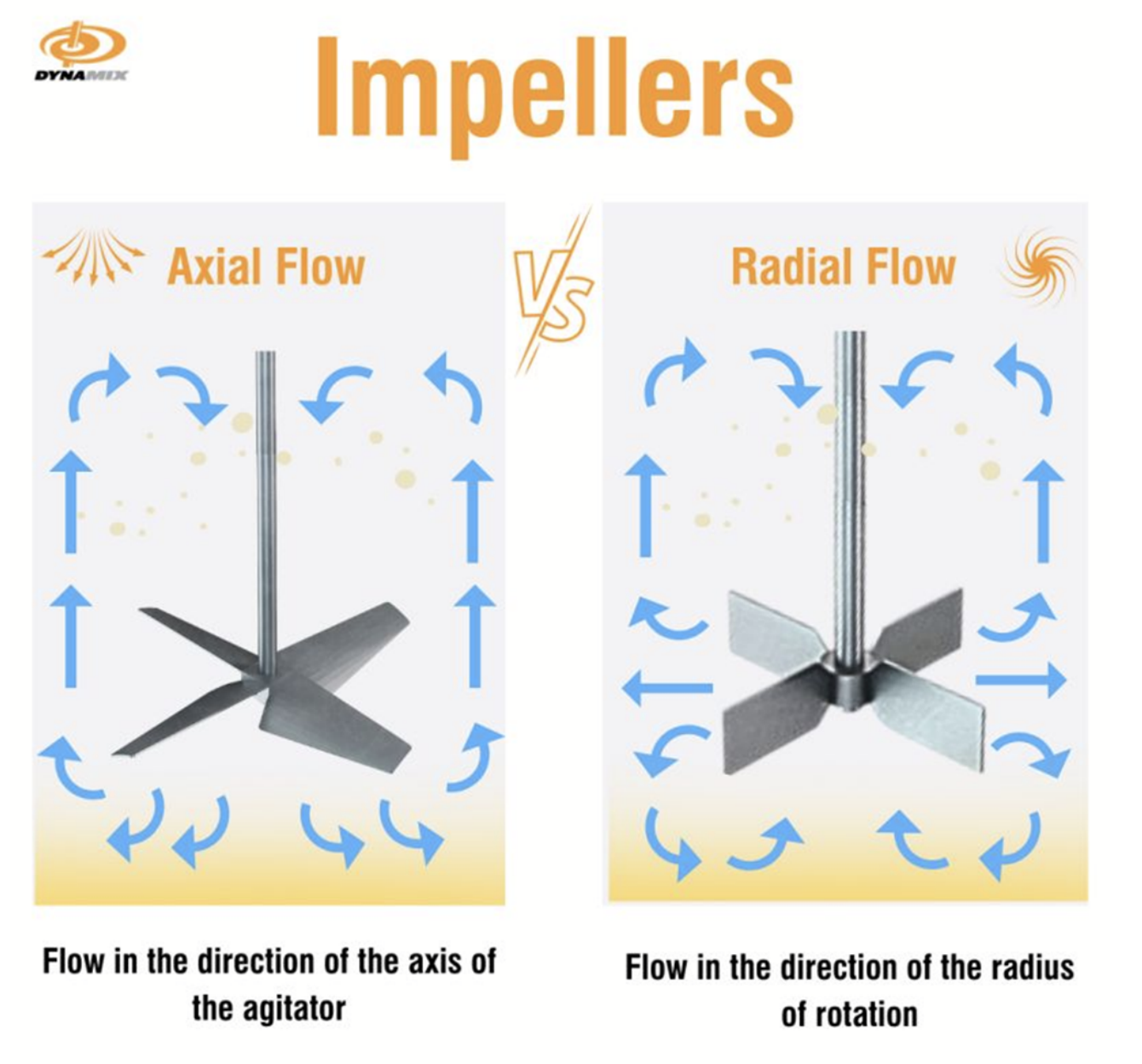
| Feature | Axial flow impeller | Radial flow impeller |
|---|---|---|
| Discharge direction | Parallel to drive shaft (downward/axial) | Perpendicular to shaft (outward to walls) |
| Primary mechanism | High volumetric pumping rate () | High localized shear stress () |
| Turbulent power number () | Low (–) | High (–) |
| Shear sensitivity | Low shear (gentle mixing) | High shear (aggressive breakup) |
| Gas dispersion capability | Poor (prone to gas cavity flooding) | Excellent (effective bubble breakup, high ) |
| Primary process use | Cell suspension, animal/plant cell culture, blending | Aerobic bacterial fermentation, gas-liquid mass transfer |
| Standard examples | Marine propeller, pitched-blade turbine (PBT), hydrofoil (Lightnin A310) | Rushton 6-flat-blade turbine, paddle agitator |
Types of impellers
| Impeller | Flow | Shear | Best for | Remember | |
|---|---|---|---|---|---|
| Rushton turbine | Radial | High | Aerobic microbial fermentation — top transfer | Highest shear/ of the six — never for shear-sensitive cells | |
| Marine propeller | Axial | Low | – | Mammalian / plant cell culture | Default gentle axial choice for delicate cultures |
| Hydrofoil (A310) | Axial | Low–moderate | – | Energy-efficient mixing, microbial + cell culture | Lowest /power draw of the six — most energy-efficient |
| Pitched blade turbine | Axial | Moderate | — | Viscous fluids, suspensions, enzymatic reactions | Only one that runs both up- and down-pumping |
| Anchor | Tangential | Low | — | High-viscosity, wall-scraping (gels, creams) | Close-clearance, tangential — scrapes wall to prevent fouling |
| Helical ribbon | Axial / helical | Low | — | Very high-viscosity, non-Newtonian fluids | Thickest, most viscosity-challenged fluids of the six |
Rushton turbine
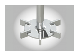
Highest shear of the six — not recommended for animal cells (shear-sensitive, no cell wall).
Marine propeller
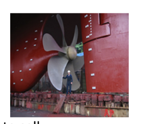
Gentle axial flow — default choice for delicate (mammalian/plant) cultures.
Hydrofoil impeller (e.g., A310)
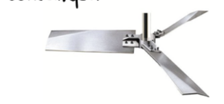
Lowest power draw of the axial impellers — efficient mixing at moderate shear.
Pitched blade turbine
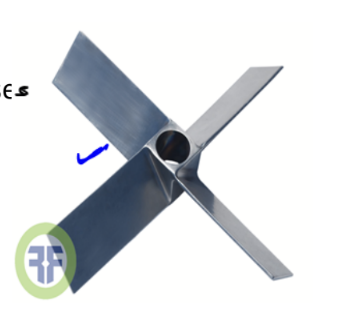
Only impeller here that runs in both up-pumping and down-pumping configurations.
Anchor impeller
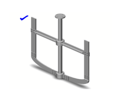
A close-clearance impeller: blades match the tank wall's curvature and scrape it directly, running in the tangential flow regime to prevent boundary-layer fouling — the only one here built to prevent wall buildup.
Helical ribbon impeller
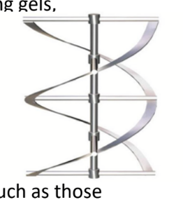
Ribbon blade spirals around the shaft — for the thickest, most viscosity-challenged fluids of the six (polymerization mixtures, biomass slurries).
Why it beats anchor at extreme viscosity: cavern formation. A turbulent impeller (Rushton, propeller) needs inertia-driven eddies to carry momentum away from the blade — that only works at high Reynolds number. Past roughly –, flow around such an impeller is deep in the laminar (creeping-flow) regime: it churns only a small cavern of fluid immediately around itself, leaving the rest of the vessel — especially near the walls — stagnant. Anchor's close clearance fixes the wall-film part of this (it scrapes the boundary layer directly), but at the highest viscosities even the anchor's bulk turnover is too weak to reach the mid-radius, mid-height fluid. Helical ribbon solves this by spanning the full height and diameter of the vessel, dragging the entire cross-section in a continuous top-to-bottom screw motion — the standard choice once viscosity climbs high enough that anchor alone can no longer prevent stagnant zones.
Worked example: impeller choice for a highly viscous mycelial broth
Question. A fermentation of Aspergillus niger produces a broth with viscosity exceeding (). Which impeller configuration best maintains bulk liquid motion and prevents stagnant zones near the wall: (a) single Rushton turbine at the bottom, (b) helical ribbon impeller, (c) high-speed marine propeller, or (d) a vibrating disc sparger?
Solution.
- Filamentous fungi like A. niger grow as mycelial networks or pellets, producing highly viscous, shear-thinning (pseudoplastic) broth — this is the extreme end of the viscosity ladder.
- At , flow around any impeller is in the laminar (creeping-flow) regime — turbulent-style impellers (Rushton, propeller) cannot propagate motion past a small cavern around the blade, so most of the tank, especially near the wall, stays stagnant. This rules out (a) and (c).
- A sparger distributes gas; it does not drive bulk liquid circulation, so (d) is the wrong category of equipment for this question.
- Helical ribbon spans the full height and diameter of the vessel and stays close to the wall along its entire helix, mechanically dragging the whole cross-section top-to-bottom — the standard impeller for broths past the viscosity where even anchor's bulk turnover is sufficient.
Answer: (b) Helical ribbon impeller.
Key points
- Turbulence is a spectrum of eddy sizes: the impeller feeds kinetic energy into the largest eddies, it cascades down to progressively smaller ones, and viscous dissipation into heat happens almost entirely at the smallest (Kolmogorov microscale) eddies.
- Shear damage is worst near the impeller blades, where the smallest, most energetic eddies form — this is what fragments filamentous fungal hyphae and lyses wall-less animal cells.
- Mixing time should be minimized — a slow mix lets local pH or concentration spikes near the addition point kill nearby cells.
- Baffles break circulatory flow and vortex formation, converting it into turbulence and eddies; a standard reactor uses 4.
- Power number () is constant only in turbulent flow — in laminar flow it depends on Reynolds number, so always check the flow regime first.
- Flow number () scales with while power number scales with — the two formulas look alike but respond very differently to impeller size.
- Radial (Rushton) impellers give high shear and high transfer; axial impellers (propeller, hydrofoil, pitched blade) give low-to-moderate shear and high pumping — never use Rushton for shear-sensitive cultures.
- Viscosity ladder for impeller choice: pitched blade → anchor → helical ribbon, as fluids get thicker and more non-Newtonian; anchor is the only one built to scrape the tank wall.