Heat Transfer
Modes of heat transfer
There are three modes of heat transfer: conduction, convection, and radiation. Radiation is out of syllabus for this section.
Conduction
Conduction is heat transfer that occurs through the transfer of vibrational energy between molecules, or through the movement of free electrons. No mobility or movement of matter is involved in conduction.
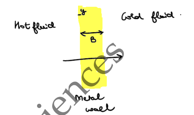
Rate of heat transfer by conduction
- — rate of heat transfer (thermal energy crossing area per unit time), in watts ()
- — thermal conductivity of the wall, in watts per metre-kelvin ()
- — area perpendicular to heat transfer, in square metres ()
- — temperature gradient, in kelvin per metre ()
- — temperatures either side of the wall, in kelvin ()
- — distance component of thickness, in metres ()
The first form is differential — it holds at a point, for the local gradient . Integrating it across a wall of constant thickness and conductivity gives the second, finite-thickness form, which swaps the gradient for the finite difference across the whole wall.
The negative sign shows that heat is transferred from the hot side to the cold side. In the finite-thickness form, the sign in front of depends on which temperature is subtracted first:
- Subtracting : use a negative sign.
- Subtracting : use a positive sign.
Either way, the final value of comes out positive.
Convection
Convection is heat transfer that occurs through the movement of molecules.
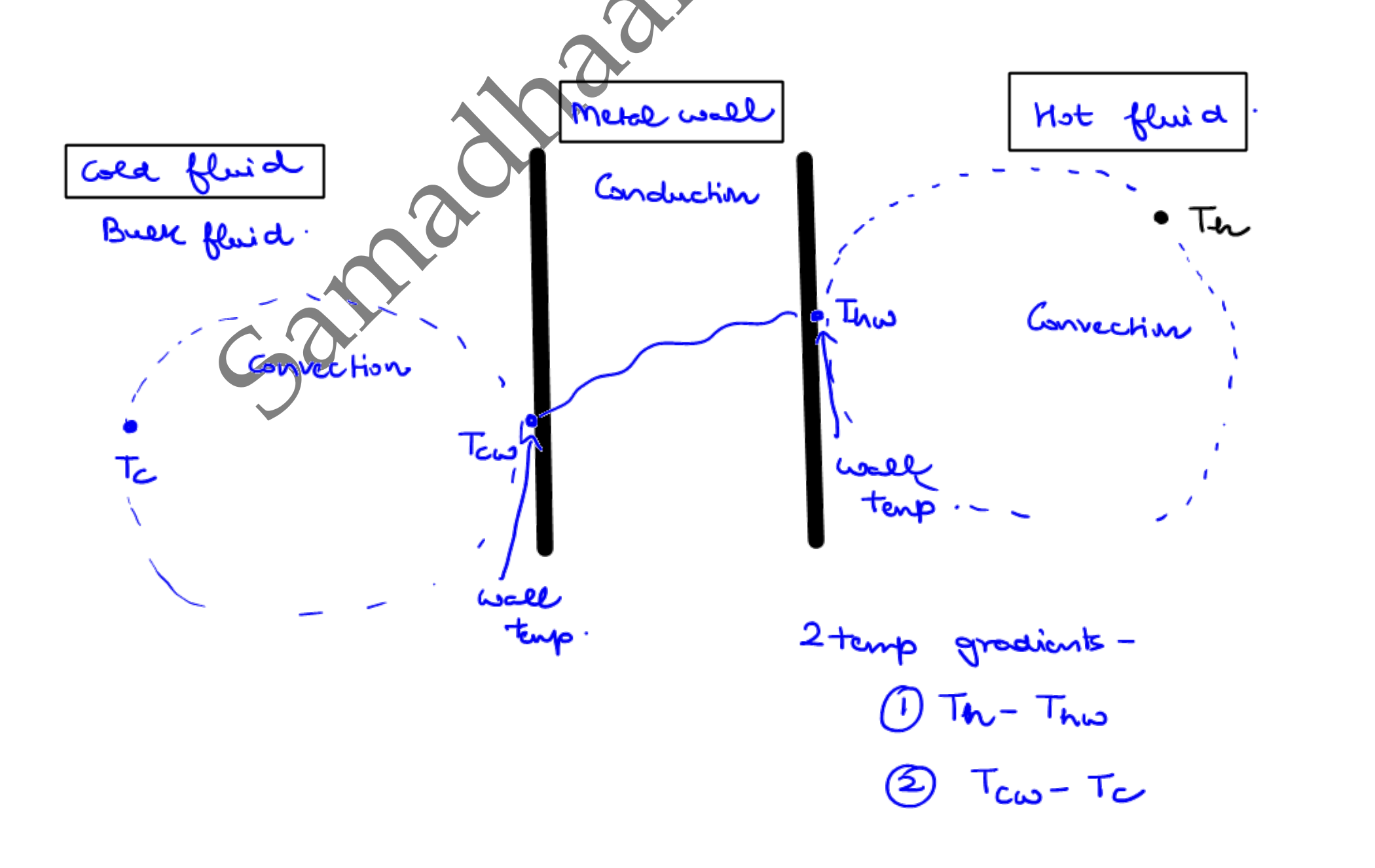
Heat crossing from a hot bulk fluid to a cold bulk fluid through a wall moves in three steps:
- Convection — hot bulk fluid () to the hot-side wall temperature ().
- Conduction — through the wall, from to the cold-side wall temperature ().
- Convection — to the cold bulk fluid ().
Two temperature gradients drive the two convective steps:
- — convection in the hot fluid.
- — convection in the cold fluid.
Rate of heat transfer by convection
- — rate of heat transfer (thermal energy crossing area per unit time), in watts ()
- — individual (film) heat transfer coefficient — how readily heat crosses between the bulk fluid and the wall by convection, in watts per square metre-kelvin ()
- — area, in square metres ()
- — temperature gradient, in kelvin ()
depends on:
| Factor | Effect on |
|---|---|
| Higher flow velocity / agitation (more turbulence) | Increases — thins the boundary film |
| Lower viscosity (e.g. higher temperature) | Increases — less resistance to flow near the wall |
| Thicker fluid film / boundary layer | Decreases — more stagnant layer to conduct across |
| Higher thermal conductivity of the fluid | Increases |
| Fouling, biofilm, or cake buildup at the wall | Decreases — adds a stagnant insulating layer (captured separately as ) |
Worked example: which changes increase h in a stirred-tank bioreactor
Question. Which of the following operational modifications will increase the inside convective heat transfer coefficient () in a stirred tank bioreactor? (a) Increasing the impeller agitation speed (b) Increasing the broth temperature (which lowers viscosity) (c) Accumulation of a dense mycelial wall cake (d) Decreasing the broth flow velocity past the heat exchange surface.
Solution.
- (a) Increasing agitation speed — raises turbulence and flow velocity at the wall, thinning the boundary film. Increases .
- (b) Increasing broth temperature (lower viscosity) — less resistance to flow near the wall, effectively raising the Reynolds number. Increases .
- (c) Mycelial wall cake — a solid, low-conductivity layer stuck to the wall acts as fouling: it adds resistance and dampens turbulence at the surface. Decreases .
- (d) Decreasing flow velocity — less turbulence, thicker boundary film. Decreases .
Answer: (a) and (b) increase ; (c) and (d) decrease it.
Nusselt number
The Nusselt number is the ratio between convective heat transfer and conductive heat transfer.
- — Nusselt number (ratio of convective to conductive heat transfer), dimensionless
- — individual heat transfer coefficient, in watts per square metre-kelvin ()
- — diameter of the pipe or tank, or characteristic length of the pipe, in metres ()
- — thermal conductivity of the bulk fluid, in watts per metre-kelvin ()
Prandtl number
The Prandtl number is the ratio of momentum diffusivity (kinematic viscosity, ) to thermal diffusivity (). Dividing both by cancels it out, leaving — the form actually used below.
- — Prandtl number (ratio of molecular momentum to thermal diffusivity), dimensionless
- — heat capacity, in joules per kilogram-kelvin ()
- — viscosity of the bulk fluid, in pascal-seconds ()
- — thermal conductivity of the bulk fluid, in watts per metre-kelvin ()
In these problems the chain typically runs backwards from what you want: to get you need ; to get you need the Nusselt number; to get the Nusselt number you need ; and for you use .
Conductive resistance of a wall
Conductive (thermal) resistance is how much a layer of material resists heat flow, per unit area — thicker or less-conductive material resists more, the same logic as electrical resistance.
- — conductive thermal resistance per unit area, in square metre-kelvin per watt ()
- — thickness of the layer, in metres ()
- — thermal conductivity of the layer's material, in watts per metre-kelvin ()
For a composite wall (several layers stacked in the direction of heat flow, e.g. a metal shell plus insulation), each layer's resistance adds, the same as resistors in series:
- — total conductive resistance of the composite wall per unit area, in square metre-kelvin per watt ()
- — thickness and thermal conductivity of layer , in metres () and watts per metre-kelvin () respectively
If convective film resistances aren't negligible, they add into the same sum as terms — see the overall- equation below, which is exactly this same series-resistance idea with the film coefficients included.
Worked example: composite bioreactor wall
Question. A composite bioreactor wall has an inner stainless steel sheet (, ) and outer insulation (, ). Convective resistances are negligible. Find the total conductive resistance per unit area.
Solution.
- Steel: .
- Insulation: .
- (to 3 d.p.) — the insulation dominates since its conductivity is lower than the steel's.
Answer: .
Overall heat transfer coefficient
The chain above requires measuring at each interface inside the bioprocess reactor, which is very difficult to measure. A newer methodology avoids this, using the overall heat transfer coefficient (), in watts per square metre-kelvin ().
Rate of heat transfer using U
- — rate of heat transfer (thermal energy crossing area per unit time), in watts ()
- — overall heat transfer coefficient (lumps both film coefficients and the wall's own conduction resistance into one number, avoiding the need to measure at each internal interface), in watts per square metre-kelvin ()
- — area, in square metres ()
- — logarithmic mean temperature difference, in kelvin ()
Overall heat transfer coefficient from film coefficients
- — overall heat transfer coefficient (lumps both film coefficients and the wall's own conduction resistance into one number), in watts per square metre-kelvin ()
- — individual film heat transfer coefficients on either side of the wall, in watts per square metre-kelvin ()
- — thickness of the wall, in metres ()
- — thermal conductivity of the wall, in watts per metre-kelvin ()
- — fouling resistance at a film surface (e.g. microbial biofilm or scale buildup), in square metre-kelvin per watt ()
All four terms are resistances in series, so is their sum — the same logic as resistors in series. Unlike , , and , is not a fixed property: it starts near zero on a clean surface and grows over the run as biofilm, protein deposits, or scale build up, steadily lowering for the same equipment. Clean-in-place (CIP) cycles reset back toward zero; equipment is often sized against an assumed fouled so it still performs adequately near the end of a cleaning cycle.
Logarithmic mean temperature difference (LMTD)
- — logarithmic mean temperature difference (single equivalent driving-force temperature for the whole exchanger, replacing the that actually varies along its length), in kelvin ()
- — temperature differences at the two ends of the heat exchanger, in kelvin ()
Special case — equal terminal differences. When , the formula above is (indeterminate). Taking the limit as shows the log mean converges to the arithmetic mean, so in that case.
Flow arrangement: parallel vs. counter-current
and depend on how the hot and cold fluids are routed through the exchanger:
- Parallel flow (co-current): both fluids enter at the same end and exit at the same end.
- Counter-current flow: the hot fluid's inlet pairs with the cold fluid's outlet, and the hot fluid's outlet pairs with the cold fluid's inlet.
Worked example: LMTD for parallel vs. counter-current flow
Question. A hot fluid enters a heat exchanger at and leaves at . A cold fluid enters at and leaves at . Find the LMTD for (a) parallel flow and (b) counter-current flow.
Solution.
-
Parallel flow (co-current) — both fluids enter at the same end, so the inlet ends pair together and the outlet ends pair together:
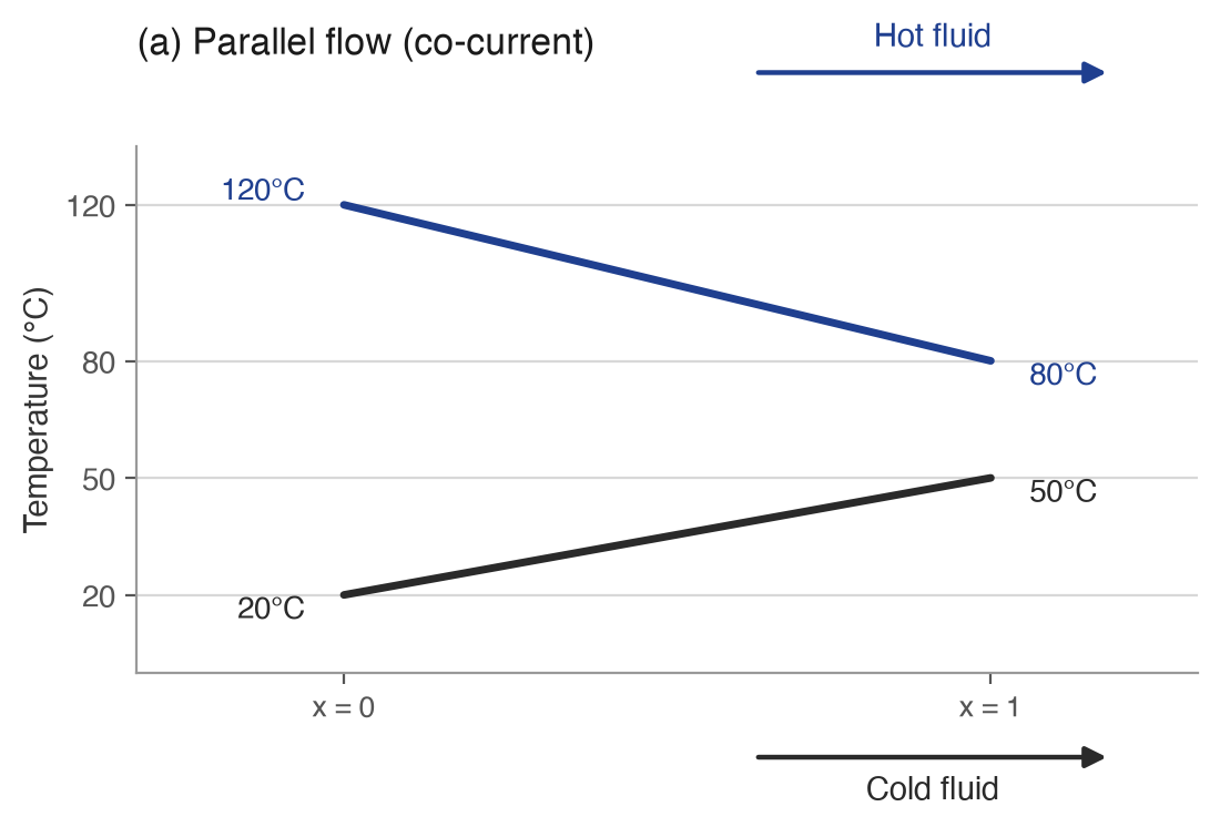
- (both inlets)
- (both outlets)
-
Counter-current flow — the hot inlet pairs with the cold outlet, and the hot outlet pairs with the cold inlet:
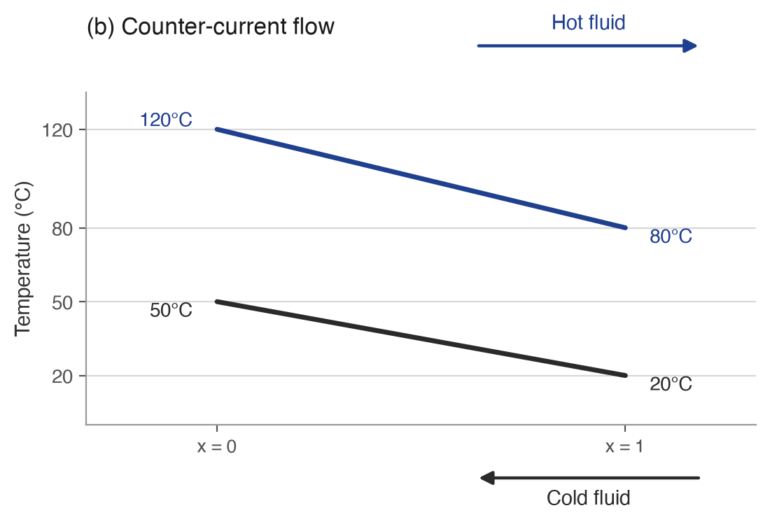
- (hot inlet, cold outlet)
- (hot outlet, cold inlet)
Answer: LMTD for parallel flow, and for counter-current flow — the counter-current arrangement gives the larger LMTD for the same four terminal temperatures.
Worked example: LMTD when the terminal differences are equal
Question. A counter-current heat exchanger cools hot oil from to using cooling water that heats from to . Find the LMTD.
Solution.
- Counter-current flow: the hot inlet pairs with the cold outlet, and the
hot outlet pairs with the cold inlet.
- (hot inlet, cold outlet)
- (hot outlet, cold inlet)
- , so is . By the equal-terminal-differences limit, .
Answer: LMTD .
Why counter-current is never worse than parallel flow
For fixed terminal temperatures (same hot-in/hot-out/cold-in/cold-out), let (how much the hot fluid cools) and (how much the cold fluid warms) — both positive in any real exchanger.
- The sum is identical either way — it works out to for both arrangements. In the worked example above: parallel gives , counter-current gives — the same.
- The spread differs. For parallel flow, . For counter-current, . Since , always — parallel flow's two s are always farther apart than counter-current's, given the same sum.
The logarithmic mean of two positive numbers with a fixed sum is largest when the numbers are equal — it sits between the geometric and arithmetic mean, and moves toward the arithmetic mean as the numbers converge. Since counter-current always keeps and closer together than parallel flow does, its LMTD is always the parallel LMTD.
The one case they tie: or — one side doesn't actually change temperature, as with a condensing vapor or boiling liquid at constant temperature. Then for both arrangements and there is no difference between them. Outside that edge case, counter-current strictly wins.
Types of heat exchangers
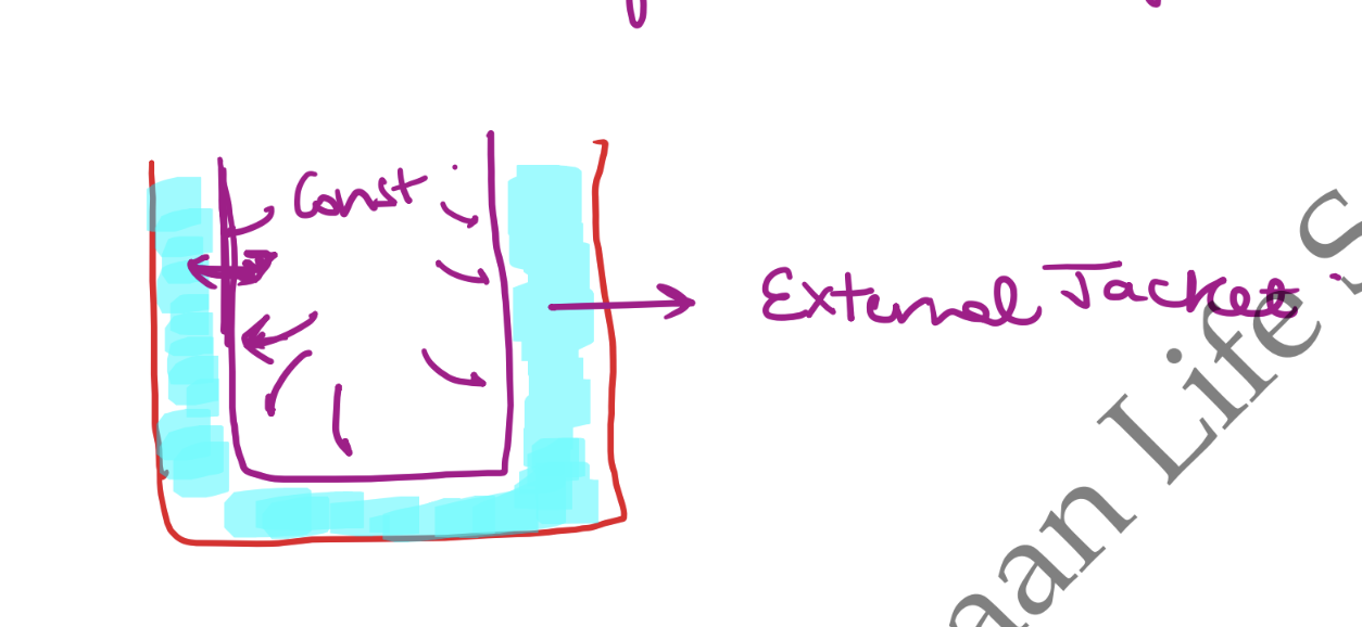
External jacket
A jacket surrounds the vessel wall, and heat transfers into or out of the vessel through that wall without the jacket fluid making physical contact with the process fluid.
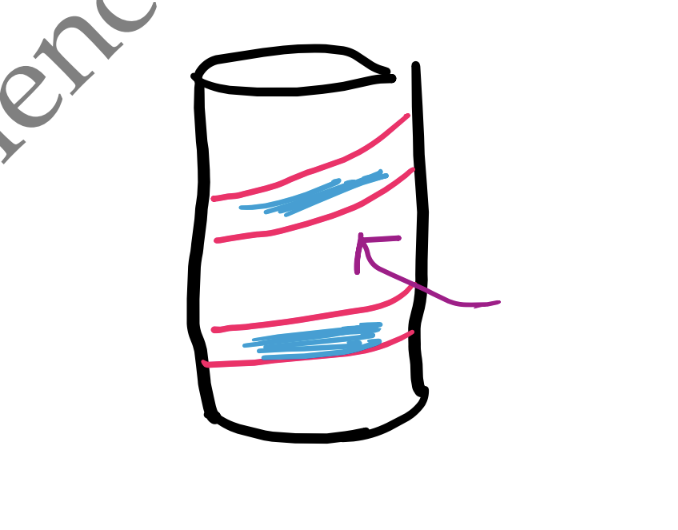
External coil
A coil wraps around the outside of the vessel wall instead of a full jacket.
Internal coil (large scale)
At large scale, a coil is placed inside the vessel, submerged in the process fluid.
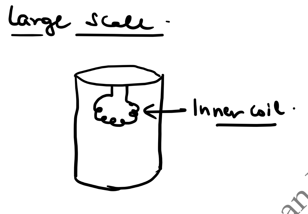
An internal coil has disadvantages: media can deposit on the coil surface, and the coil increases shear on the process fluid.
Double pipe (tube-within-tube) heat exchanger
A double pipe heat exchanger is a tube-within-tube arrangement — one fluid flows through the inner cylinder, the other through the space between the inner and outer cylinder.
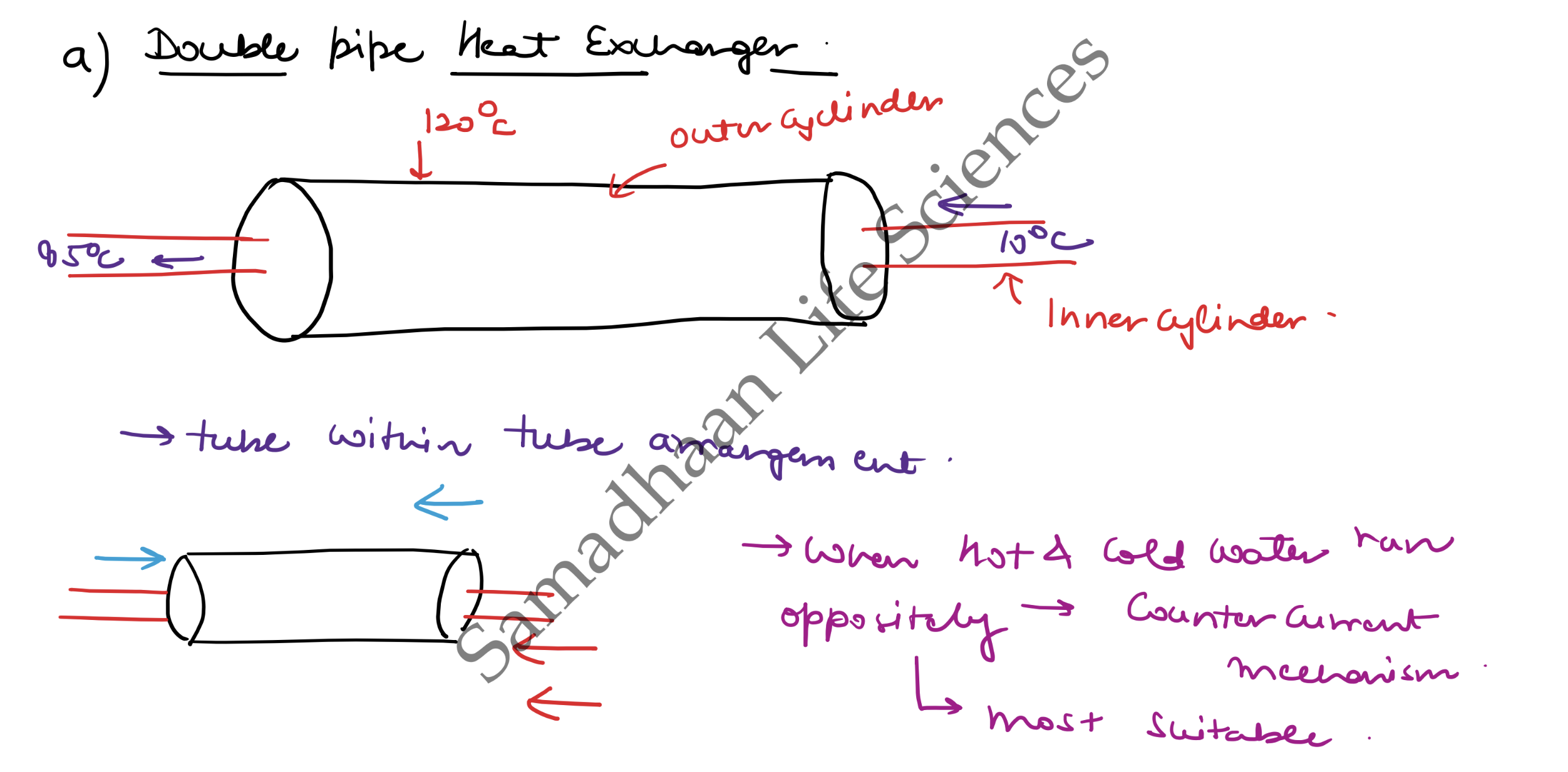
When the hot and cold fluids run opposite each other, this is the counter-current mechanism — double pipe heat exchangers are the most suitable arrangement for it.
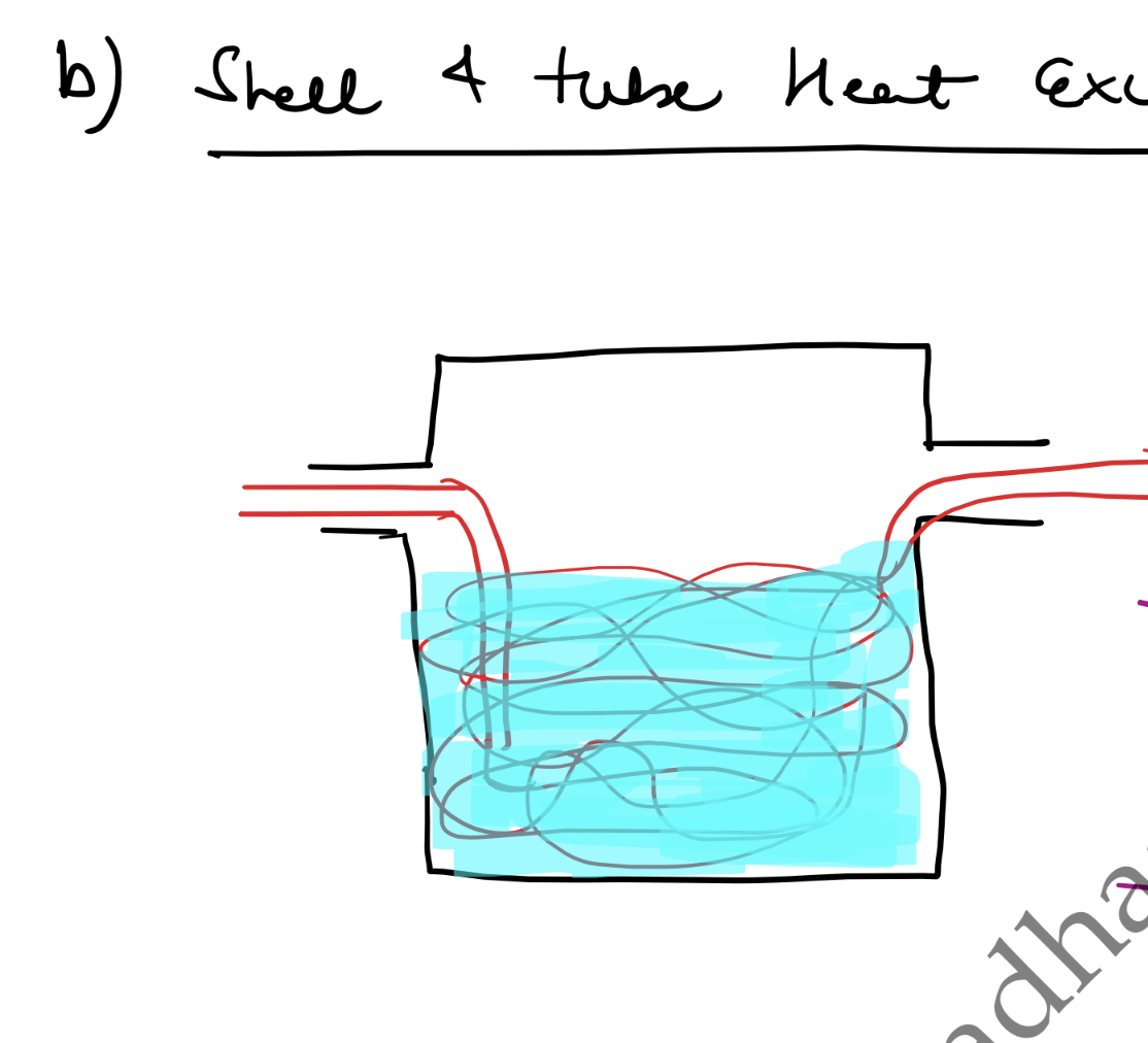
Shell and tube heat exchanger
A shell and tube heat exchanger is used when a large amount of heat exchange is required. A bundle of tubes carrying one fluid passes through a shell cavity holding another fluid.
Heat generation and removal in bioprocesses
Aerobic fermentations generate metabolic heat as respiration proceeds, on top of any mechanical heat added by agitation — cooling equipment has to remove both, and metabolic heat is what usually dominates at scale.
Metabolic heat from oxygen consumption (Cooney's correlation)
Heat release tracks oxygen consumption because both come from the same respiratory electron-transport reactions — the more the culture consumes, the more heat it releases.
- — metabolic heat released by aerobic respiration, in kilojoules ()
- — heat released per mole of oxygen consumed (Cooney's correlation), approximately ( , since )
- — moles of oxygen consumed by the culture ()
Scale-up heat transfer challenge
- — cooling surface area available (jacket or coil), in square metres ()
- — reactor working volume, in cubic metres ()
- — characteristic vessel diameter, in metres ()
Reactor volume scales with but the wall area available for cooling only scales with , so the specific cooling area falls as . Metabolic heat generation scales roughly with volume (more broth, more respiring cells), so larger fermenters generate heat faster than their jacket area can remove it — the classic bioreactor scale-up cooling bottleneck.
Jacket vs. internal cooling coil
| Feature | External jacket | Internal cooling coil |
|---|---|---|
| Cooling area | Limited to the vessel wall | Extra area, added independently of vessel wall size |
| Shear on cells | Low — no extra internal surfaces | Higher — coil surface adds turbulence near the cells |
| Working volume | Unaffected | Reduced — the coil itself occupies working volume |
| Typical use | Default choice; preferred for shear-sensitive cultures (e.g. animal cells) | Added at large scale when jacket area alone can't remove enough heat, for shear-tolerant microbial cultures |
Worked example: evaluating heat generation and removal statements
Question. Select the correct statements regarding heat generation and removal in aerobic bioprocesses: (a) Aerobic microbial growth is accompanied by heat release proportional to the rate of oxygen consumption. (b) The heat of fermentation can be estimated using Cooney's correlation: approximately per mole of consumed (or per g of ). (c) Scale-up of stirred fermenters creates heat transfer challenges because reactor volume scales with , while surface area for cooling scales with . (d) Internal cooling coils are preferred over external jackets for highly shear-sensitive animal cell cultures to minimize volume.
Solution.
- (a) Metabolic heat comes from the same respiratory reactions that consume , so heat release tracks the oxygen uptake rate. Correct.
- (b) This is exactly Cooney's correlation above: . Correct.
- (c) and , so specific cooling area falls as — the standard scale-up cooling bottleneck. Correct.
- (d) Backwards on both counts: external jackets, not internal coils, are preferred for shear-sensitive cultures, precisely because coils add internal turbulence/shear and reduce usable working volume rather than minimizing it. Incorrect.
Answer: (a), (b), and (c) are correct; (d) is incorrect.
Key points
- Conduction moves heat via vibrational energy or free electrons, with no movement of matter; the sign on Fourier's law only tracks direction — itself always comes out positive.
- Heat crossing a jacketed wall moves in three steps: convection (bulk fluid to wall), conduction (through the wall), convection (wall to bulk fluid) — driven by two separate s, one per convective step.
- Nusselt number () is the convective-to-conductive heat transfer ratio; Prandtl number () is the momentum-diffusivity-to-thermal-diffusivity ratio — the calculation chain runs , backwards from what you actually want.
- Overall heat transfer coefficient avoids measuring at each wall interface: combines both film coefficients with the wall's own conduction resistance.
- . For fixed terminal temperatures, is identical for parallel and counter-current flow, but counter-current keeps and closer together — so its LMTD is always parallel flow's, never smaller.
- The two arrangements only tie when one fluid doesn't change temperature at all (a condensing vapor or boiling liquid) — otherwise counter-current always wins.
- Metabolic heat tracks oxygen consumption — Cooney's correlation: ().
- Scale-up hurts cooling because but cooling area , so ; external jackets stay the default (and are preferred for shear-sensitive cultures), while internal coils add area at large scale at the cost of extra shear and working volume.